WHATS INCLUDED IN YOUR KIT
There are a lot of small components included in the kit so please open the packaging carefully and check that all parts are present and correct using the parts list below before you start.
| PCB | |
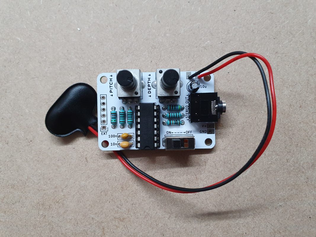
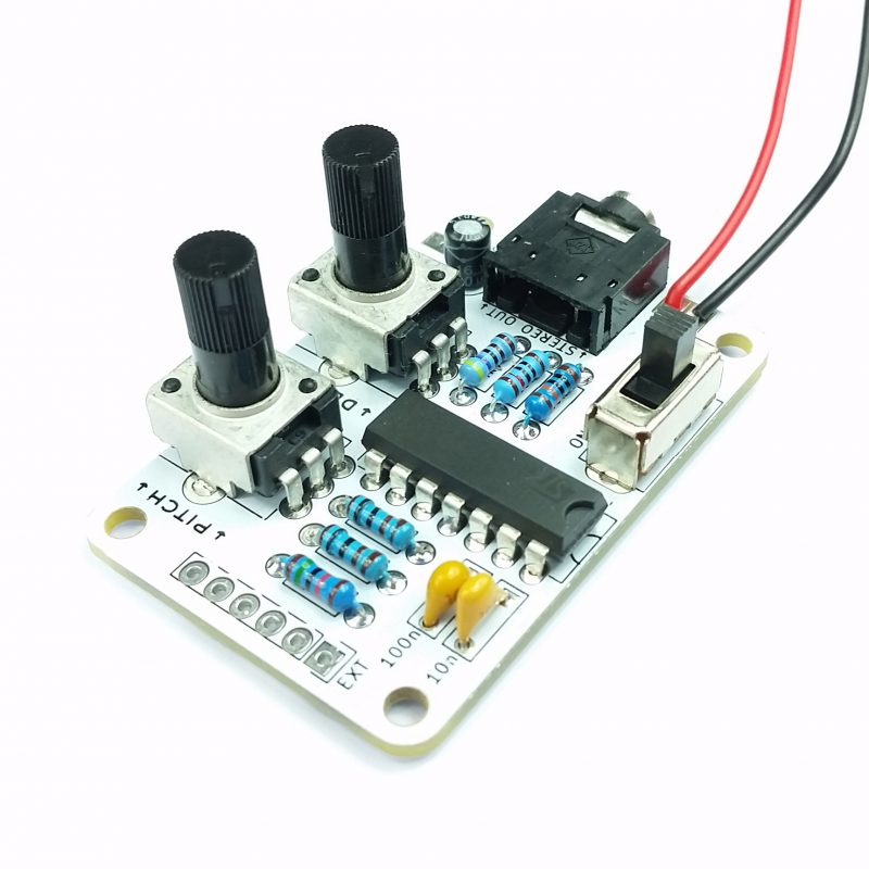
| 500k Potentiometer | 2 |
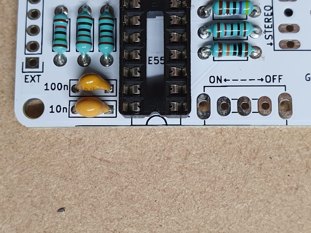
| NE556 Dual 555 Timer IC | 1 |
| 100k Resistor | 1 |
| 15k Resistor | 1 |
| 10k Resistor | 1 |
| 1k Resistor | 2 |
| 4.7k Resistor | 1 |
| 10uF Electrolytic Capacitor | 1 |
| 9V Battery Snap | 1 |
| 10nF Ceramic Capacitor | 1 |
| 100nF Ceramic Capacitor | 1 |
| On/Off Switch | 1 |
| 3.5mm Stereo Jack | 1 |
let's get started
YOU WILL NEED:
Soldering Iron (and solder)
Flush Cutters
Good Lighting
Optional but handy..
Pliers
Blu-Tack
Multi-meter
Pliers are handy to bend component legs. Blu Tack can be used to keep the circuit board and component in place while soldering.

USING A Multi-meter?
To check your resistors, set your multi-meter to the Ohm (Ω) setting and place the probes across the resistor.
Chances are the resistors will be bang on, or really close to one of the values in the kit. Verify this for yourself by checking the colour codes on the resistors and the provided cheat sheet.
At Rakit we use both colour code identification and multi-meter measurements when coming up against resistor values we don’t instantly recognise.
The double check can really help, especially with values that are multiples of others. But don’t worry! You definitely don’t need a multi-meter to assemble a kit.

ORGANISE
Organisation… boo! (But seriously, take your time)
Try to enjoy the process of soldering and getting organised.
Soldering in a methodical process will set you up for success. Whats more, you’ll gain the confidence to take on more complicated soldering tasks in the future.