Click here to download

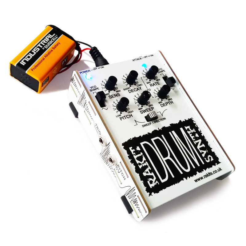
The Rakit Drum Synth is based on the (now rare) Boss PC-2/AMDEK PCK-100 percussion synthesizer with extra modifications including:

*Attack on/off

*VCO & LFO wave shape selection

*Pitch CV input

The synth is triggered by a piezo disc which is sensitive to how hard you tap the top panel giving subtle differences in the envelope. The sounds are generated by a VCO (Voltage Controlled Oscillator) optionally modulated by a frequency sweep, LFO (Low Frequency Oscillator), Pitch CV (Control Voltage) or all three. There is a simple envelope generator with a fixed fast attack for punchy percussive envelopes and variable decay for super short to long decays (5 seconds+). The sounds produced by the synth are perhaps not what you would normally expect to associate with drum sounds and can vary from big bass drums to tapping on glass to UFO space drum-wobbly things!

whats included in your kit

There are a lot of small components included in the Drum Kit so please open the packaging carefully and check that all parts are present and correct using the parts list below before you start.

3.5mm Mono Socket 3
A100k Log Potentiometer 4
B504 500k Linear Potentiometer 1
B102 1k0 Linear Potentiometer 1
50k Trim potentiometer 2
2.1mm/5.5mm Barrel Power Socket 1
Right Angle SPST Slide Switch 2
Horizontal DPDT Slide Switch 3
1n0 Box Capacitor 4
3n3 Box Capacitor 1
22n Box Capacitor 1
47n Box Capacitor 3
100k 0.6W 1% Resistor 11
33k 0.6W 1% Resistor 2
47k 0.6W 1% Resistor 12
22k 0.6W 1% Resistor 4
10k 0.6W 1% Resistor 5
4k7 0.6W 1% Resistor 4
390R 0.6W 1% Resistor 1
4M7 0.6W 1% Resistor 1
1k0 0.6W 1% Resistor 5
56k 0.6W 1% Resistor 1
1M0 0.6W 1% Resistor 1
220k 0.6W 1% Resistor 2
OTA IC BA6110 1
Op Amp 4558 IC 1
Op Amp 358/2904 IC 3
3mm Blue LED 2
Signal Diode 1N4148 3
Schottky diode IN5819 1
2N3904 NPN Transistor 2
2N3906 PNP Transistor 2
2SC945P NPN Transistor 2
1u0 Electrolytic Capacitor 3
10u Electrolytic Capacitor 2
100u Electrolytic Capacitor 1
PCB – Top, Inside, Left Wing, Right Wing 4
Battery Snap to Barrel 1
Rubber Tube 4

Let's get started!!

YOU WILL NEED:

Soldering Iron (and solder)

Flush Cutters

Pliers (Optional but handy)

Drum Instructions - IC Placement
Take care with the orientation of the IC's

Place the IC’s (Integrated Circuits) in the orientation shown, part identifiers shown on the silkscreen. A specially selected LM2904 has a thick white line at one end of the package. Place this upon the IC outline with a correspondingly thick black line.

Pin 1 is indicated on an 8 pin DIP (Dual Inline Package) IC by a notch at one end or a circle at one corner. The silkscreen on the PCB has these same characteristics and an additional short line parallel to pin 1 on the silkscreen.

Pin 1 is indicated on the 9 pin SIP (Single Inline Package IC) by a small indentation and an outlined pad on the silkscreen.

When placing the transistors, they must be pushed down far enough such that they won’t foul the front panel.

Level with or slightly taller than the DIP/SIP packages is fine.

Place the two 2N3906 in the positions shown carefully noting the orientation.

The flat edges should be facing towards the VCA TRIM text.

Note: The transistors will only work in the correct orientation.

Place the two 2N3904 in the positions shown carefully noting the orientation.

The flat edges should be facing towards the VCA TRIM text

Note: The transistors will only work in the correct orientation.

Place the two 2SC945P in the positions shown carefully noting the orientation.

The upper transistor flat edge should be facing the output socket.

The lower transistor flat edge should be facing upwards towards the sweep selection switch.

Note: The transistors will only work in the correct orientation.

Place the diodes, IN5189 x 1 and IN4148 x 3. Making sure the band on the diode corresponds to the band on the silkscreen.

Note: The diodes are polarity sensitive and will not work in the wrong orientation.

All diodes. transistors and IC's placed.

All diodes placed.

Page