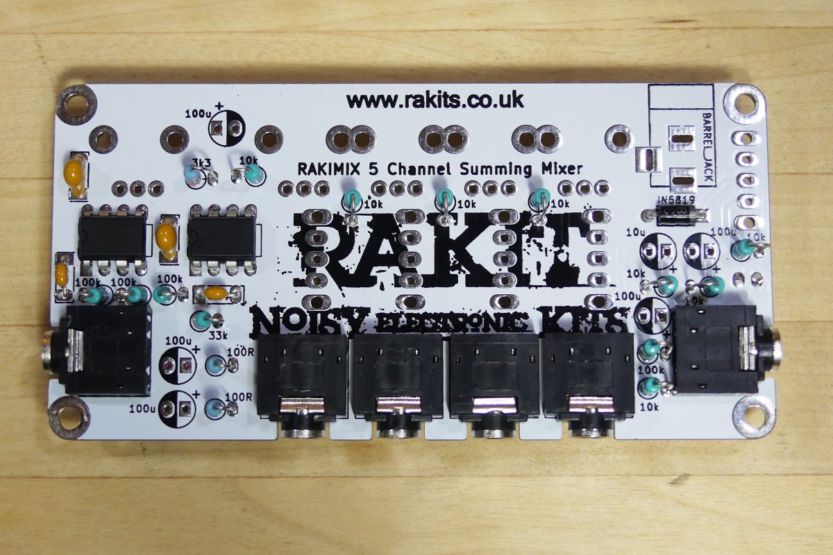
WHATS INCLUDED IN YOUR KIT
There are a lot of small components included in the Rakimix kit so please open the packaging carefully and check that all parts are present and correct using the parts list below before you start.
| PCB | 1 |
| 100k Potentiometers | 4 |
| 10k Potentiometer | 1 |
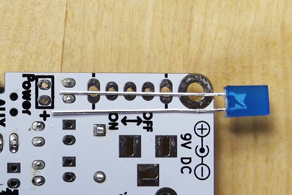
| 2x5mm LED | 1 |
| SPDT Slide Switch | 5 |
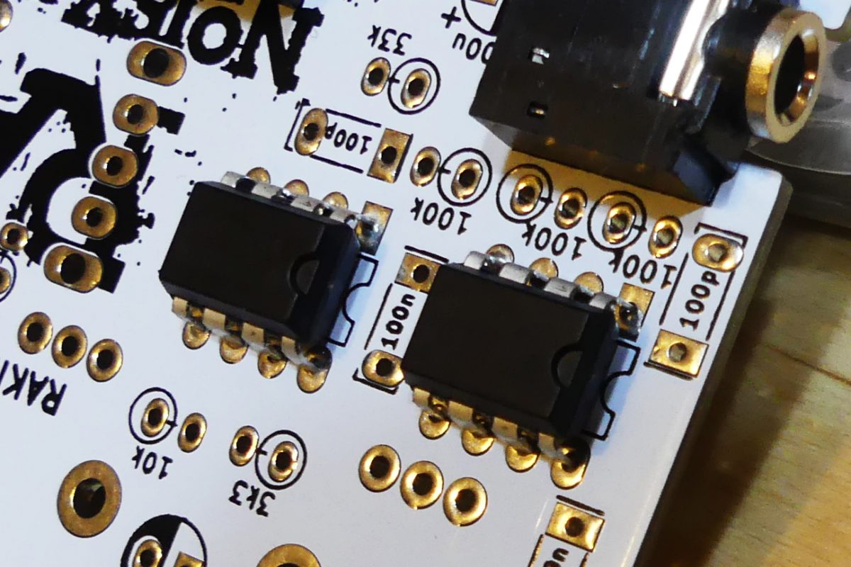
| NE5532 Op Amp | 2 |
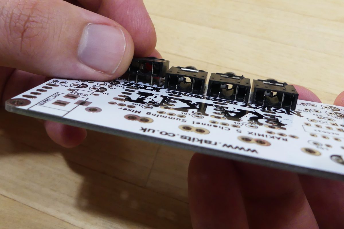
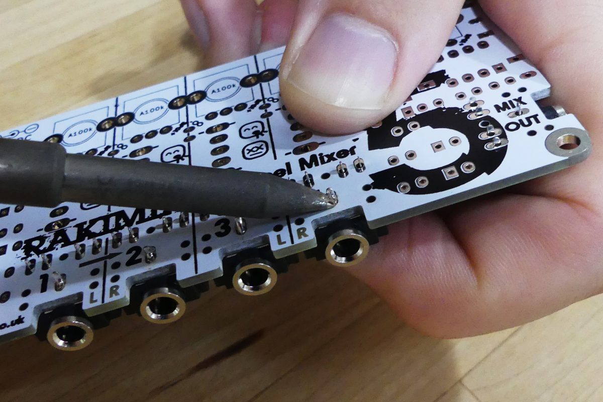
| 3.5mm Stereo Jacks | 6 |
| 100k Resistors | 4 |
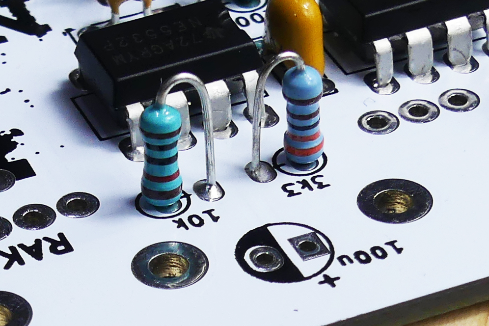
| 10k Resistors | 8 |
| 100R Resistors | 2 |
| 33k Resistors | 1 |
| 3.3k Resistors | 1 |
| Stand-offs | 4 |
| Nuts | 4 |
| 100uf Electrolytic Capacitor | 5 |
| 10uf Electrolytic Capacitor | 1 |
| Power Jack | 1 |
| 9V pp3 Battery to Barrel Jack | 1 |
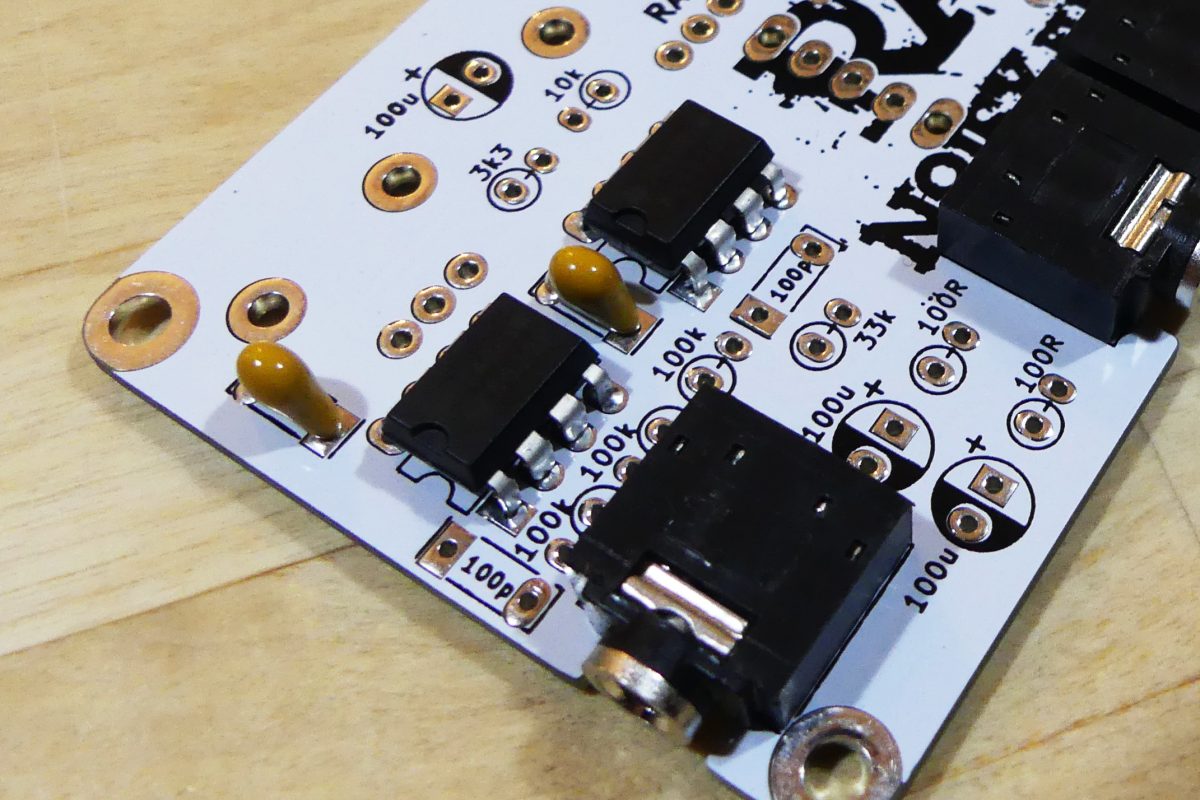
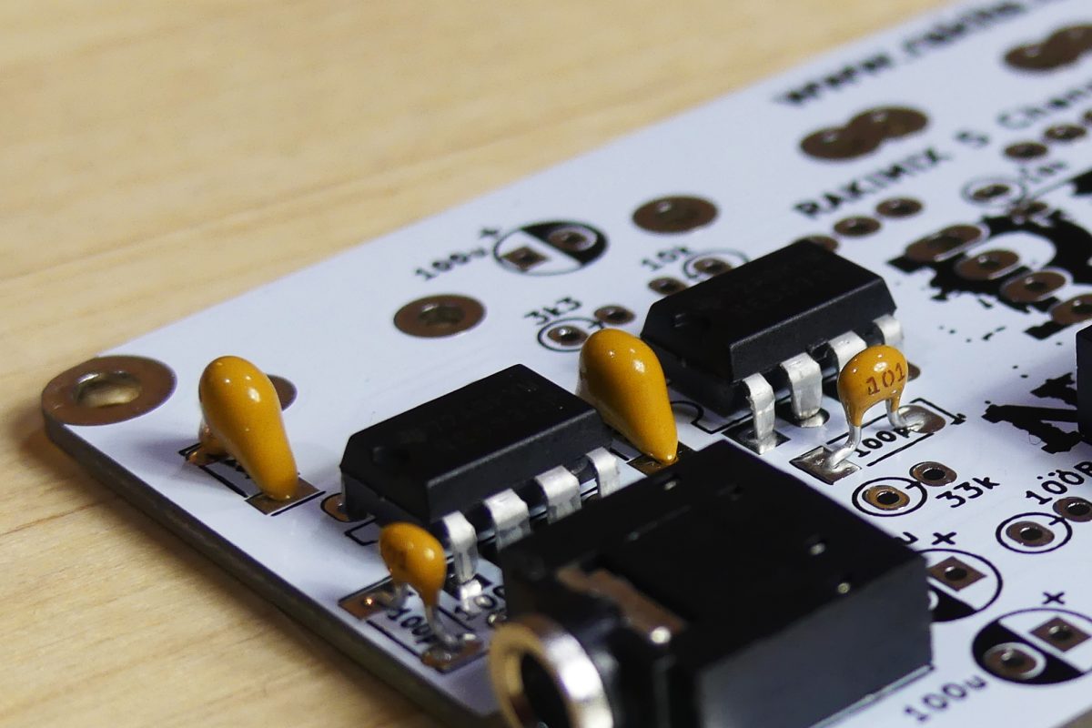
| 100p Ceramic Capacitor | 2 |
| 100nf Ceramic Capacitor | 2 |
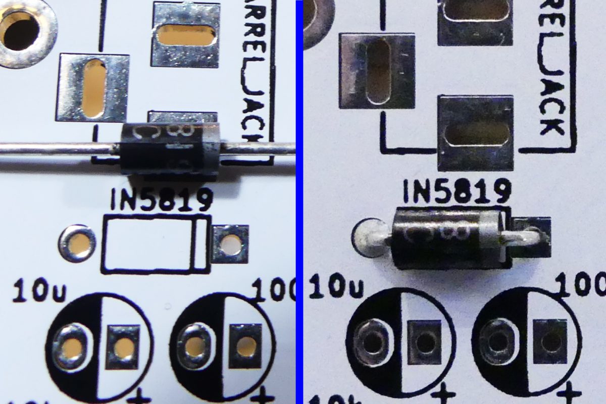
| Schottky Diode | 1 |
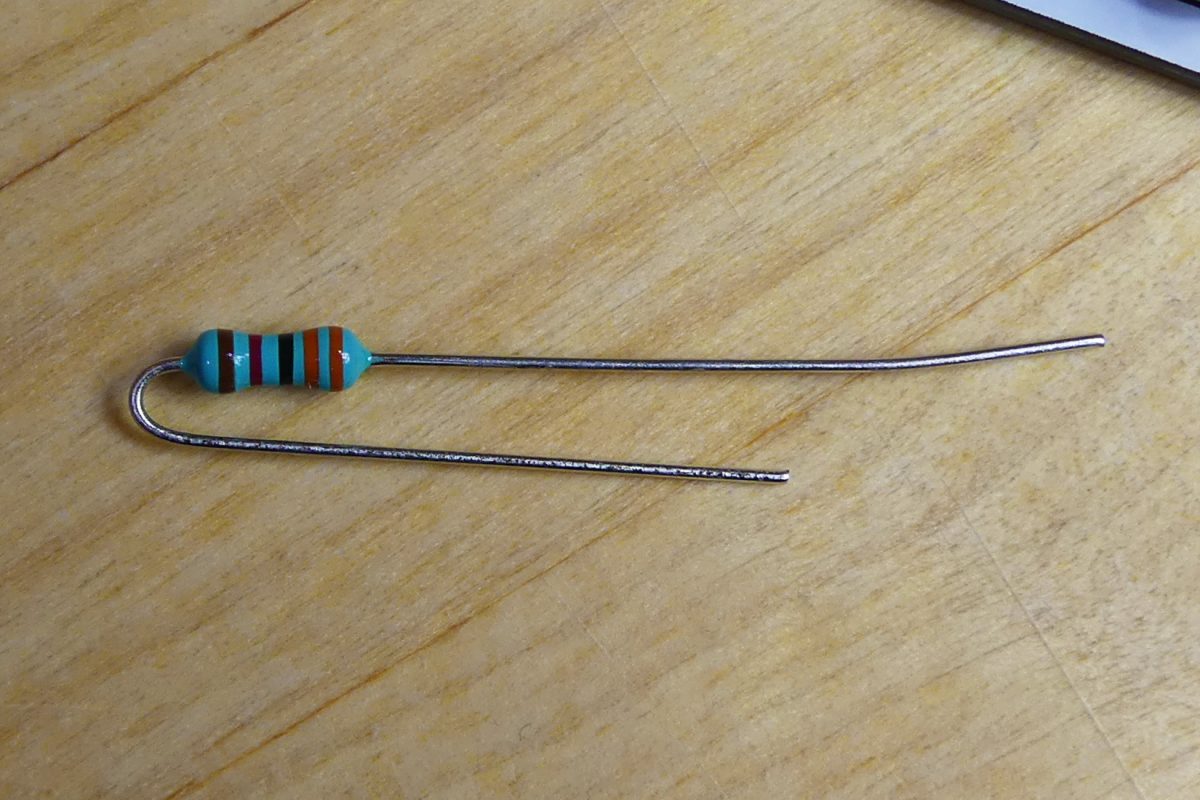
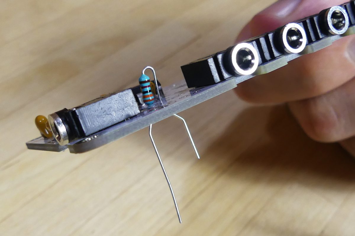
OUR TOP TIPS BEFORE YOU BEGIN:

let's get started
YOU WILL NEED:
Soldering Iron (and solder)
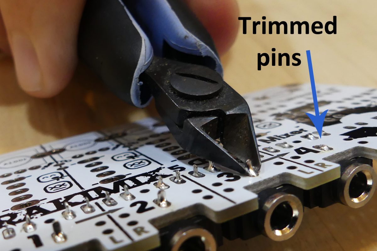
Flush Cutters
Pliers (Optional but handy)